This code module provides Quadrature
- Encoder, and
- Decoder support.
Encoder support:
Incremental encoders can be simulated with this code module.
Decoding support:
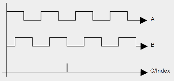
By analyzing two 90 degrees shifted signal inputs from incremental encoder sensors, rotation direction and position can be determined.
The two signals A and B in the below graph represent typical waveforms of such inputs. Signal C/Index represents the end of each complete cycle:
Depending on your required data, the QAD code module allows you to set the following parameters:
Quadrature modes:
- 1x: Counter increments at each rising edge event of signal A
- 2x: Counter increments at each rising or falling edge event of signal A
- 4x: Counter increments at each rising or falling edge event of signal A and B
Actions on Index (C)
You can define the following counter settings whenever C/Index is High (end of cycle):
- Reset on index: Counter is cleared
- Reload on index: Counter is reset with your selected init value
- Latch on index: Stores the counter value into the output register
- Index reference mode: Resets the counter to zero when the C/Index signal of the encoder is high for the first time. After this initial high C/Index signal, the QAD code module will ignore the C/Index signal and switch to "ignore index input" mode.
- Ignore index input: no action
Counting modes
- Cycling counter: defines a counter range of -2^31 to 2^31 - 1
- Divide-by-N: defines a counter range of - Steps per revolution to + Steps per revolution - 1. Each time the counter reaches the selected minimum or maximum Steps per revolution value, the counter is reset.
- Single Cycle: Counting stops when a defined counting value is met. To start counting again, a reset is required.
Steps per revolution
The number of steps can be freely configured based on your hardware specifications. Typical values are powers of two (1024, 2048, 4096, …).